
ROBOLOP BERYLLIUM BMW 323ci
 Dec 2, 2011 | 02:19 PM
#141

Thread Starter
| Teamspeed Member
Joined: Jan 2008
Posts: 179


This thing will be my mold for bending the plexiglass. The cover, that comes onto the top of the amplifier, will be round, as you can see.
The MDF (wooden) chassis:
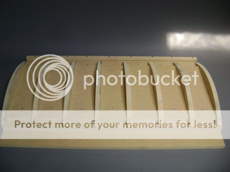
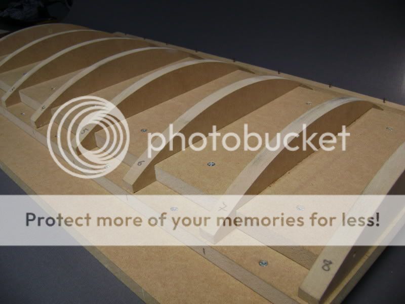
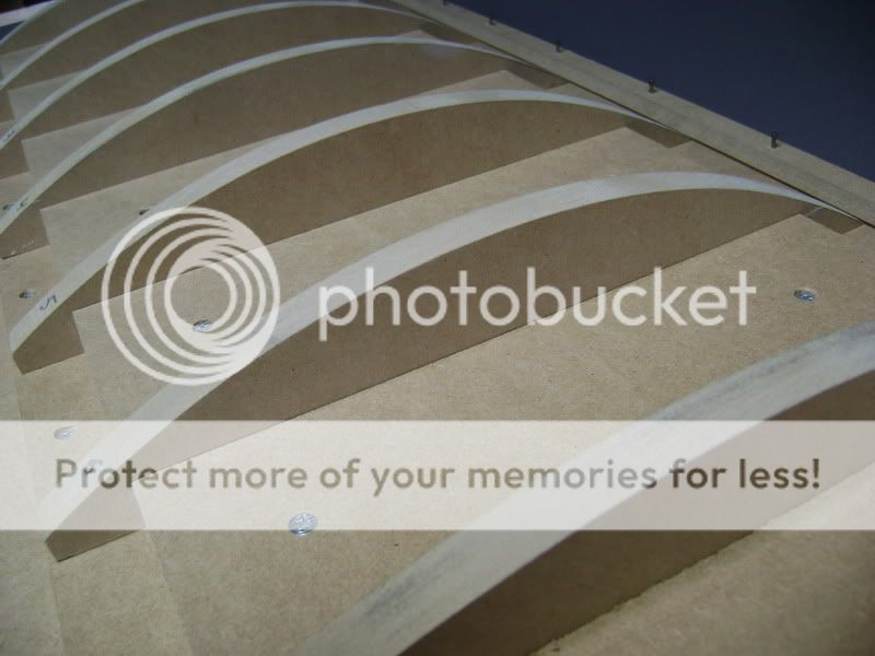
I covered this with an aluminum plate of 0.5 mm thick, so I got a nice rounding.
Also, I made it more round as it finally has to come.
Once the plexi is cooled off, it always brends a bit more straight again.
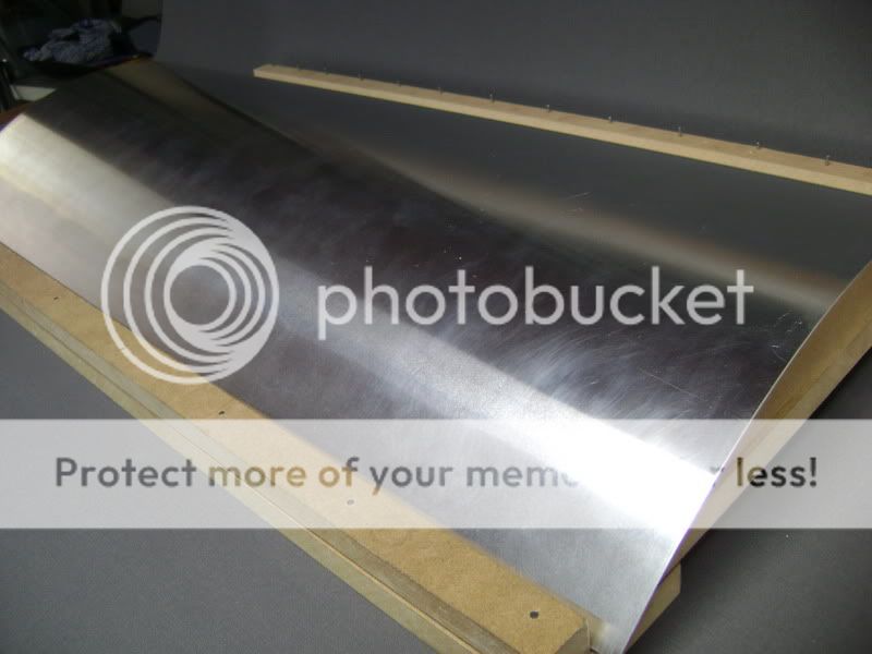
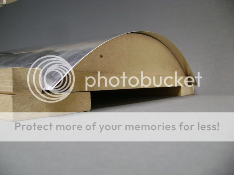

Hopefully this works, cause just on the mold, I had some reasonable work.
The MDF (wooden) chassis:
I covered this with an aluminum plate of 0.5 mm thick, so I got a nice rounding.
Also, I made it more round as it finally has to come.
Once the plexi is cooled off, it always brends a bit more straight again.
Hopefully this works, cause just on the mold, I had some reasonable work.
Dec 2, 2011 | 02:20 PM
#142
Thread Starter
| Teamspeed Member
Joined: Jan 2008
Posts: 179
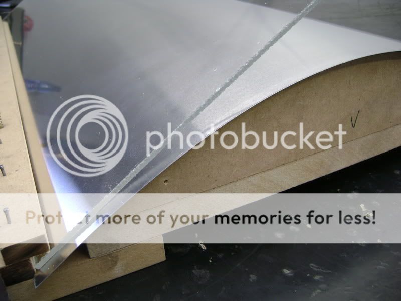
This is the plexi I folded/bended with the paintstripper.


As you can see, I didn’t go as well as planned.
The problem with the paint stripper is that I doens’t heat everything at the same time.
This wasn’t the case with the plexi of the filtercase.
Just needed one fold there, so just had to heaten only one line.
With this big piece, the plexi glass cools don’t too fast, and the temperature isn’t the same everywhere.
So actually, a piece like that, has be heated in an oven between 120 – 150 degrees Celcius.
Since I didn’t find an oven in that couple of days, I bought me a plexi plate.
You can’t boggle for long now, do we�
I think this looks mucht better already.


These two pieces come on the sides. So you’ll get the idea it’s one big, entire piece.


As you can see, I didn’t go as well as planned.
The problem with the paint stripper is that I doens’t heat everything at the same time.
This wasn’t the case with the plexi of the filtercase.
Just needed one fold there, so just had to heaten only one line.
With this big piece, the plexi glass cools don’t too fast, and the temperature isn’t the same everywhere.
So actually, a piece like that, has be heated in an oven between 120 – 150 degrees Celcius.
Since I didn’t find an oven in that couple of days, I bought me a plexi plate.
You can’t boggle for long now, do we�
I think this looks mucht better already.
These two pieces come on the sides. So you’ll get the idea it’s one big, entire piece.
Dec 2, 2011 | 02:21 PM
#143
Thread Starter
| Teamspeed Member
Joined: Jan 2008
Posts: 179
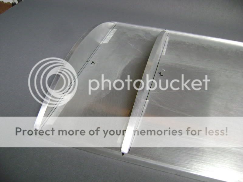
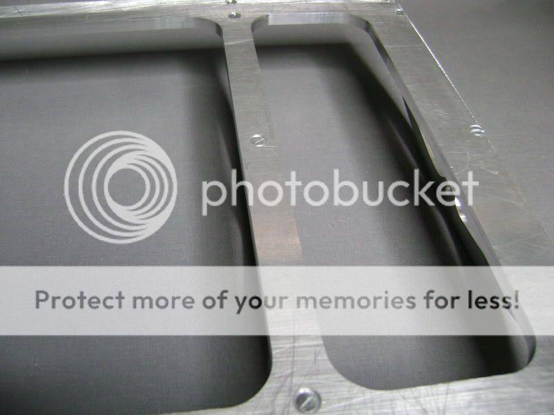
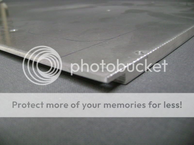
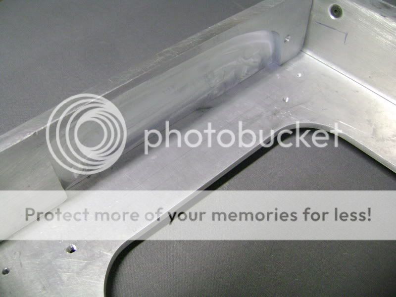
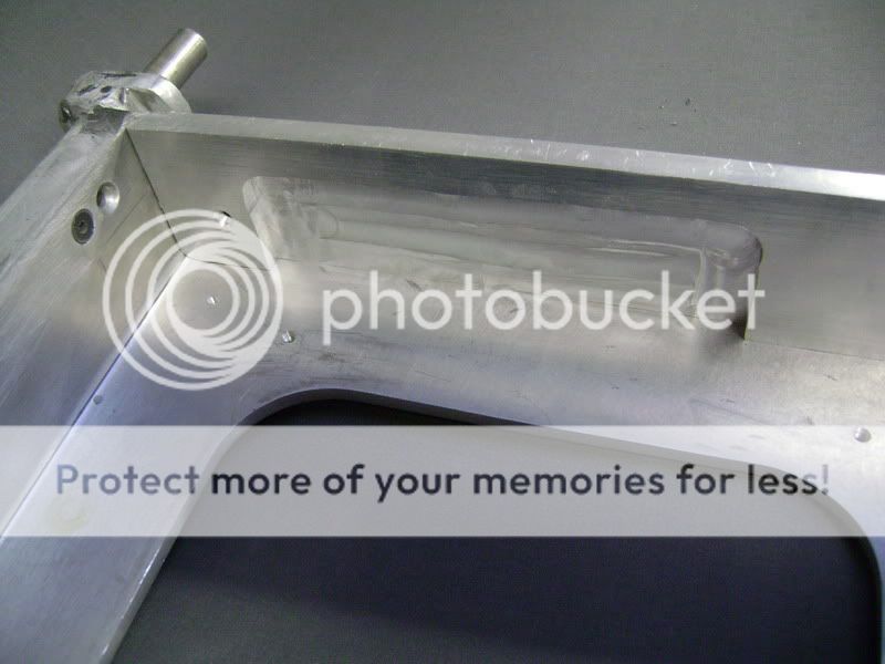
I worked some more on the two aluminum sides of the amplifier box, with the uppermill.
First tightened those thick plates.

Planted the mill.
The meaning here was to remove some millimeters, cause there has to come a carbonkevlar plate.
These are the sides that come on the outerside, to service as coverplate.
You can see on the holes, that the design here will be the same as the sides of the filtercase.I also milled away a couple of mm’s here.


Abraded it all firmly so I could polish the aluminum.
Here an example what it will look like
Have to give a rounding on these 2 plates, cause the plexi comes in between.
First tightened those thick plates.
Planted the mill.
The meaning here was to remove some millimeters, cause there has to come a carbonkevlar plate.
These are the sides that come on the outerside, to service as coverplate.
You can see on the holes, that the design here will be the same as the sides of the filtercase.I also milled away a couple of mm’s here.
Abraded it all firmly so I could polish the aluminum.
Here an example what it will look like
Have to give a rounding on these 2 plates, cause the plexi comes in between.
Dec 2, 2011 | 02:22 PM
#144
Thread Starter
| Teamspeed Member
Joined: Jan 2008
Posts: 179
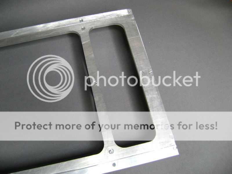
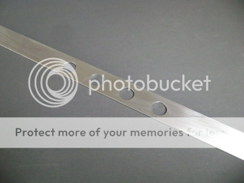
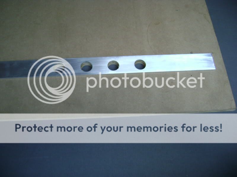
Of these pieces of aluminum I’m going to make a frame, where the plexi will rest in.
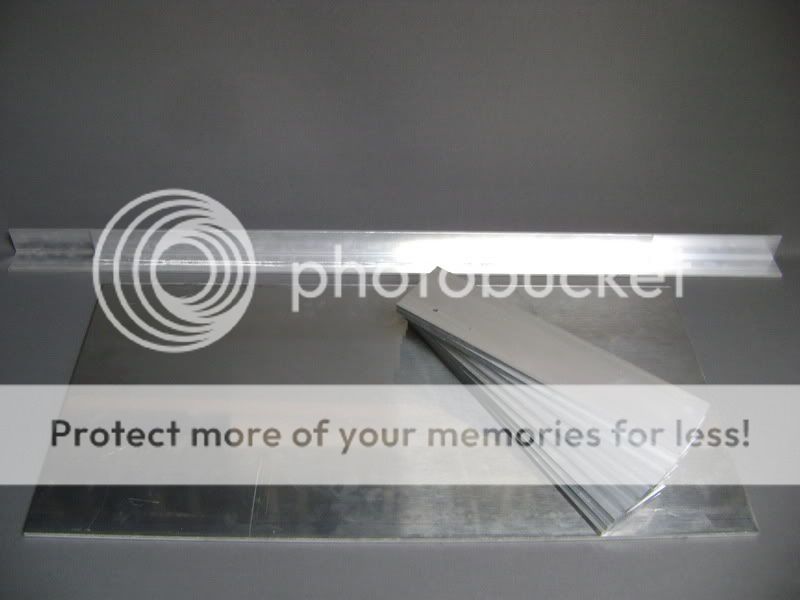
The big plate i 8mm thick
The 8 other ones are 6mm thick
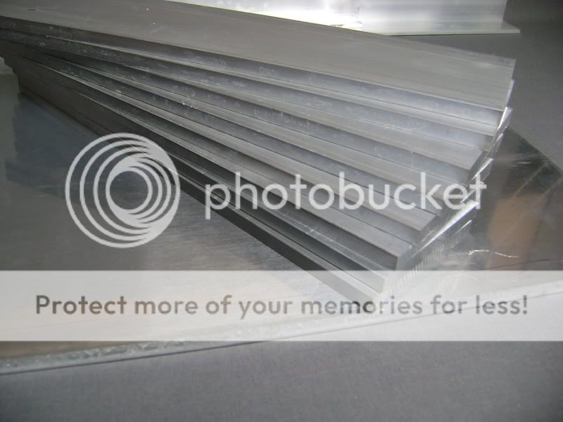
This isn’t going to be all, I’m going to use some other aluminum profiles also, but haven’t got the mesurement of those ones.
Many and many hours of millwork will get into this, but when it all works out like I have it in my head, it’ll be pretty cool.
Oh yeah, I’ll use some carbon fibre here too, but thought you gus will guessed that already..
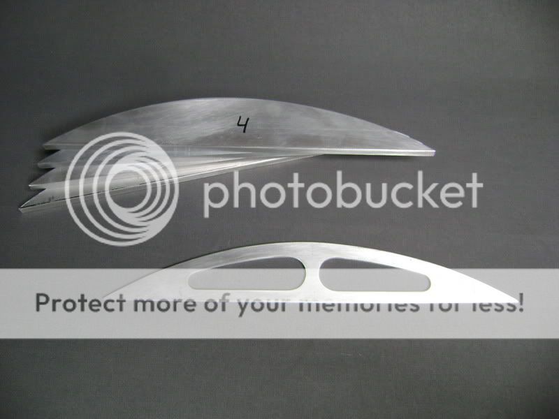
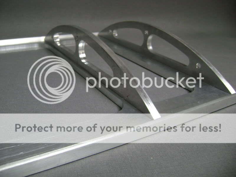
I made 4 aluminum supports of 8mm thick.
These have the same rounding as the plexi.
First, I made a mold out of mdf. After that, I drawed out the aluminum piece, and sawed it out.
after that, with double sided tape, I sticked it all together.

Once this was done, I held it all to the copy-mill
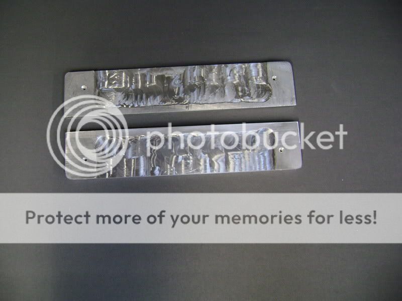
Here a picture of how it will look.

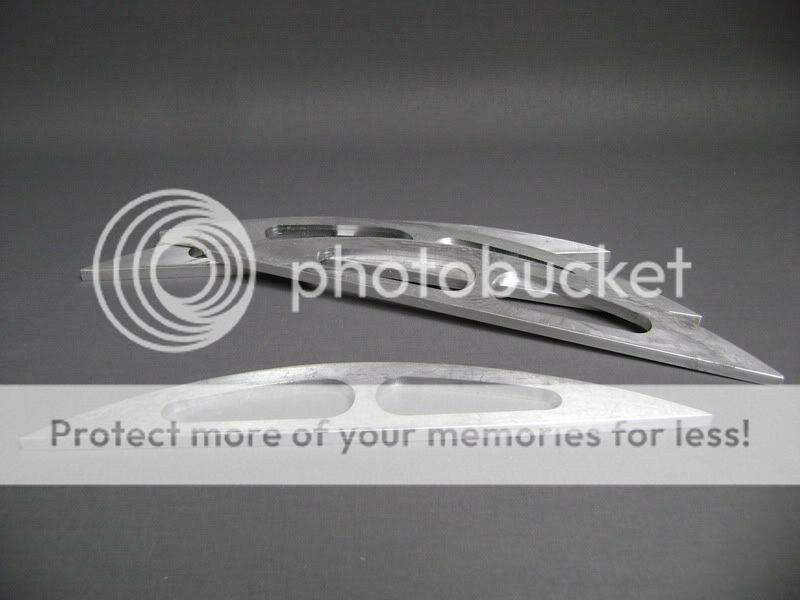
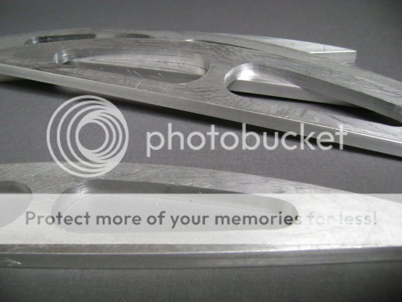
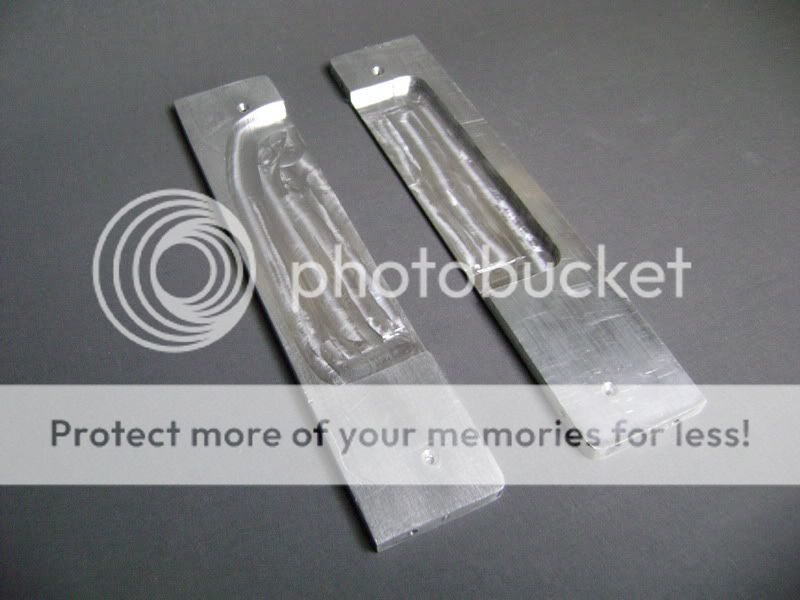
The next step was to “modify” the supports, cause it looks a bit simple like this.
The lower plate is the model I made.
It’s only 4mm thick.
In the piece I needed, I got rid off the aluminum, and sticked it all together again, and then got the mill back in there.

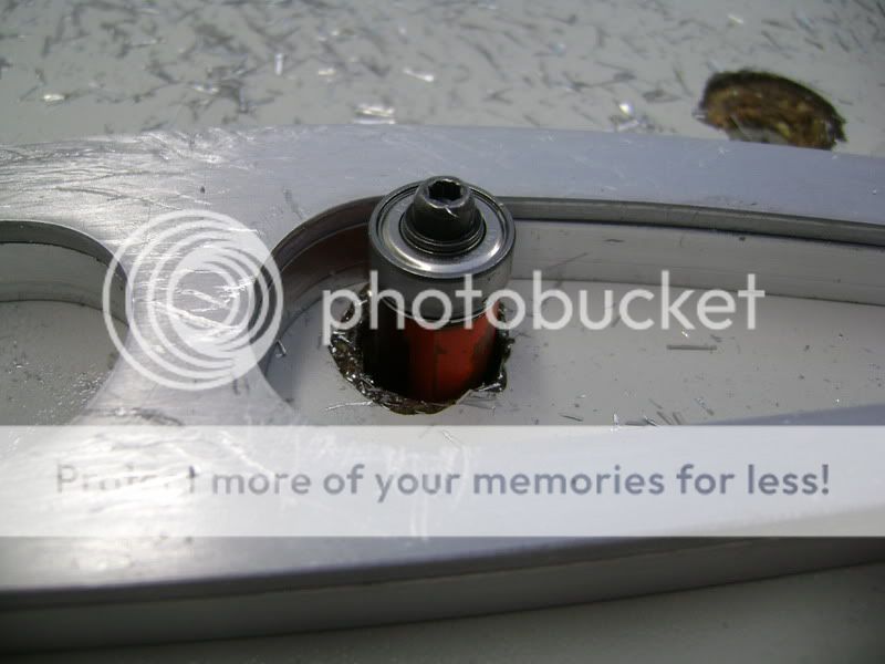
Looks way cooler according to me.


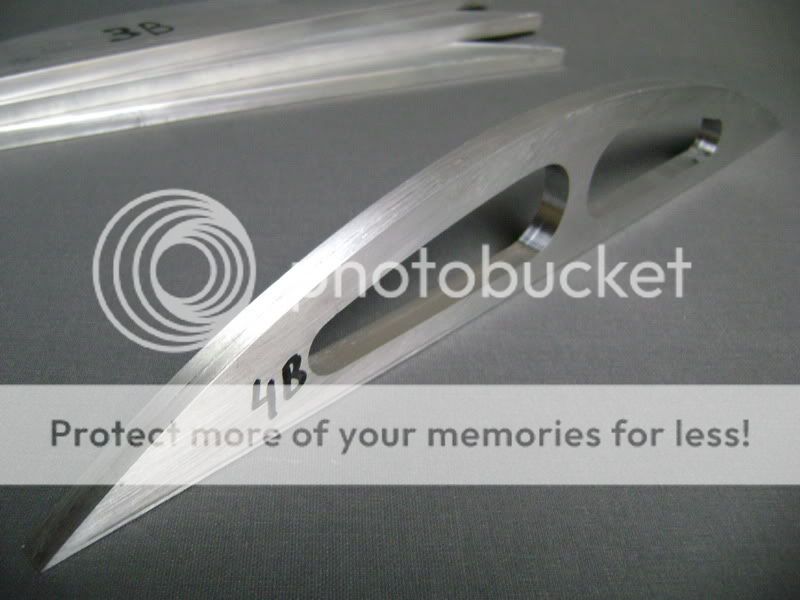
The other 3 will suffer the same cause.
The pattern looks good, but the support still doens’t look the way I wanted too�So I guess I’m going to modify this some more.
The big plate i 8mm thick
The 8 other ones are 6mm thick
This isn’t going to be all, I’m going to use some other aluminum profiles also, but haven’t got the mesurement of those ones.
Many and many hours of millwork will get into this, but when it all works out like I have it in my head, it’ll be pretty cool.
Oh yeah, I’ll use some carbon fibre here too, but thought you gus will guessed that already..
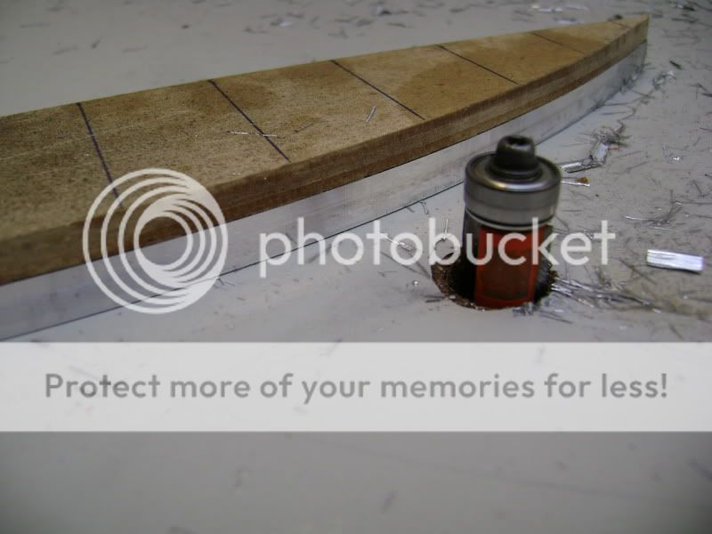
I made 4 aluminum supports of 8mm thick.
These have the same rounding as the plexi.
First, I made a mold out of mdf. After that, I drawed out the aluminum piece, and sawed it out.
after that, with double sided tape, I sticked it all together.
Once this was done, I held it all to the copy-mill
Here a picture of how it will look.
The next step was to “modify” the supports, cause it looks a bit simple like this.
The lower plate is the model I made.
It’s only 4mm thick.
In the piece I needed, I got rid off the aluminum, and sticked it all together again, and then got the mill back in there.
Looks way cooler according to me.
The other 3 will suffer the same cause.
The pattern looks good, but the support still doens’t look the way I wanted too�So I guess I’m going to modify this some more.
Dec 2, 2011 | 02:23 PM
#146
Thread Starter
| Teamspeed Member
Joined: Jan 2008
Posts: 179
Too some issues I didn't get the chance to do much on the ICE.
But now , a 'little' update.The 4 toggles where the plexi will lay on to are finished
The alu-plate of 8mm where the toggles will get onto.

Offcourse, some holes were needed here, otherwise you wouldn't be able to see the amplifier.This is the mold I made of 4mm thick MDF wood.
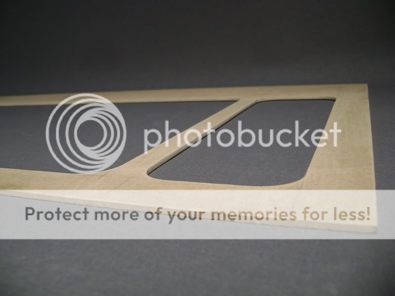
Layed this on the aluminum and drawed it out

Then, I drilled some holes, and sawed it all out with the electric jigsaw
Pasted the MDF mold on to it.


Then I mounted my upper-mill once again under the table to do some dangerous stuff


Here the result


But now , a 'little' update.The 4 toggles where the plexi will lay on to are finished
The alu-plate of 8mm where the toggles will get onto.
Offcourse, some holes were needed here, otherwise you wouldn't be able to see the amplifier.This is the mold I made of 4mm thick MDF wood.
Layed this on the aluminum and drawed it out
Then, I drilled some holes, and sawed it all out with the electric jigsaw
Pasted the MDF mold on to it.
Then I mounted my upper-mill once again under the table to do some dangerous stuff
Here the result
Dec 2, 2011 | 02:24 PM
#147
Thread Starter
| Teamspeed Member
Joined: Jan 2008
Posts: 179
Then I 'modified' the outer toggles.
Because a M6 bar with screw-thread will get into this one, I had to drill the hole much bigger, so the nut is sunk into it all.
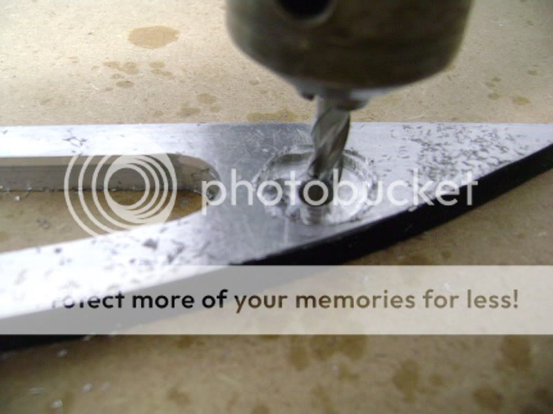
Made it big enough so it would be possible to get a 10 on there as well
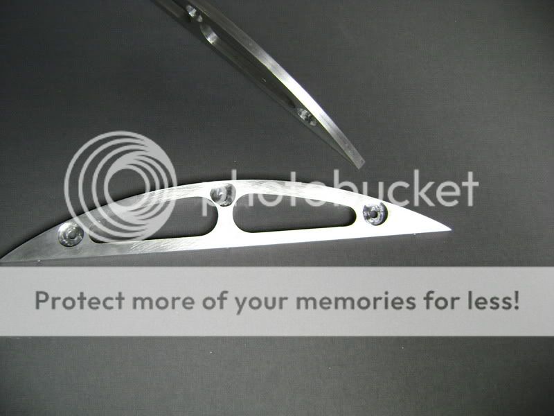

In all toggles I tapped a screw-thread of M5, to fasten them at the bottom
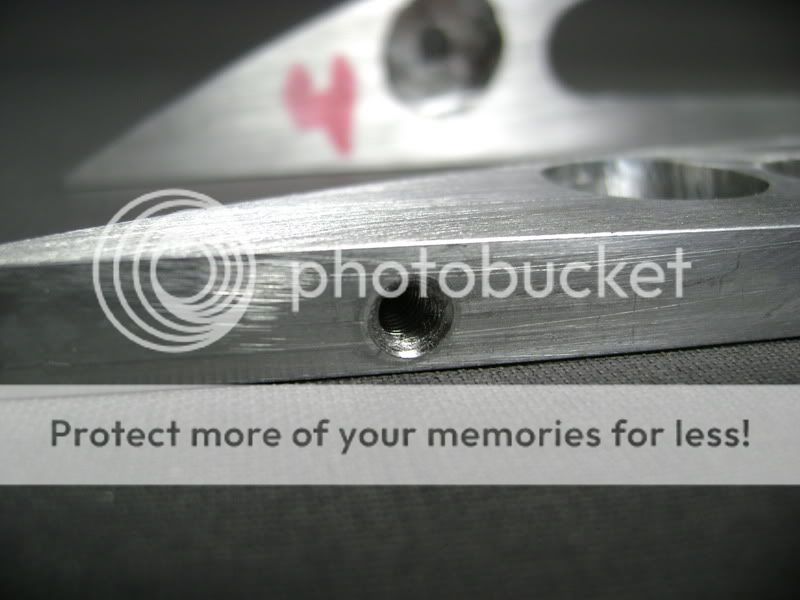
Once I had all of this, I could begin the mounting.
The front and back of the thick plate, I milled in a gap whereto I screwed a big L onto.SO I have a nice finishing touch, and the plexi is tense.
Because a M6 bar with screw-thread will get into this one, I had to drill the hole much bigger, so the nut is sunk into it all.
Made it big enough so it would be possible to get a 10 on there as well
In all toggles I tapped a screw-thread of M5, to fasten them at the bottom
Once I had all of this, I could begin the mounting.
The front and back of the thick plate, I milled in a gap whereto I screwed a big L onto.SO I have a nice finishing touch, and the plexi is tense.
Dec 2, 2011 | 02:24 PM
#148
Thread Starter
| Teamspeed Member
Joined: Jan 2008
Posts: 179
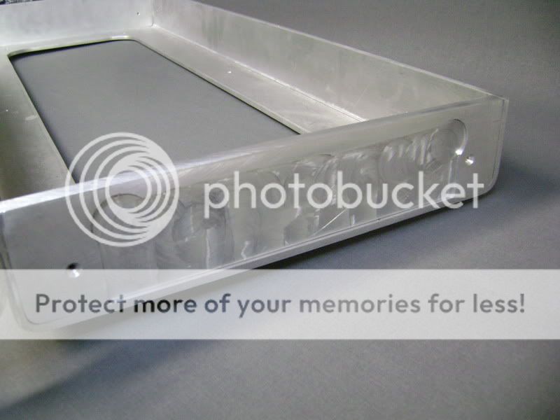
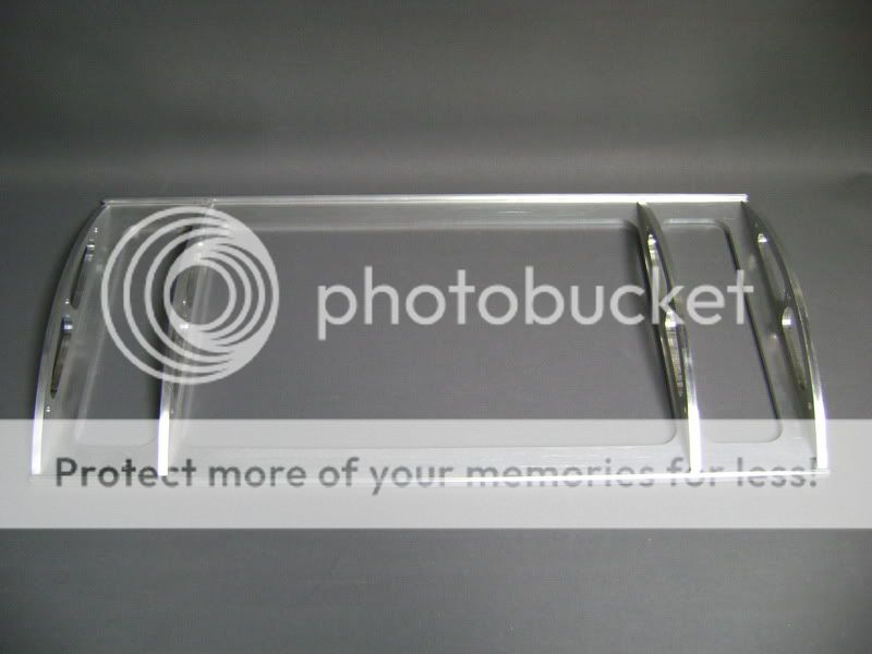
Here are some aluminum parts I'm going to work with in the cover.
The 9 tubes you see on the fore-ground are from anodised aluminum.
On the backside you see 3 threadstaff of m6
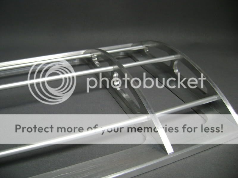
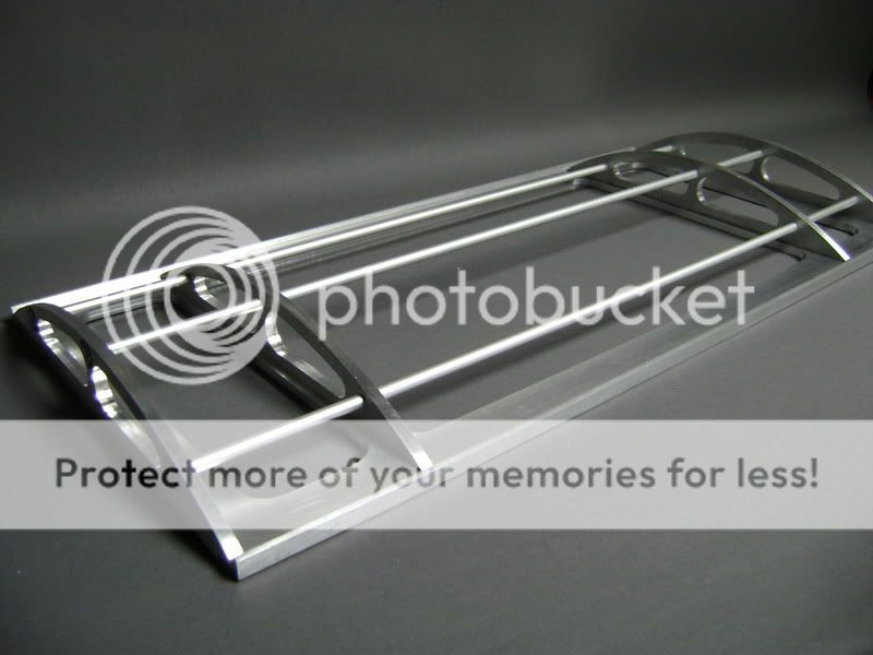
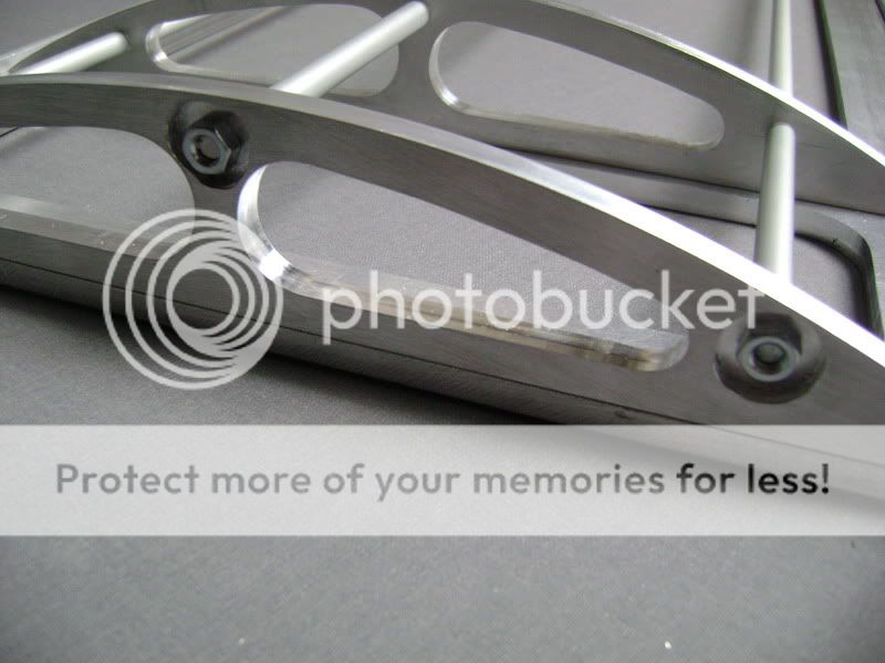
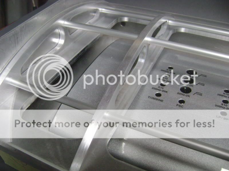
Here you see why I had to sink in the m6 screws.
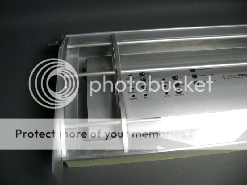
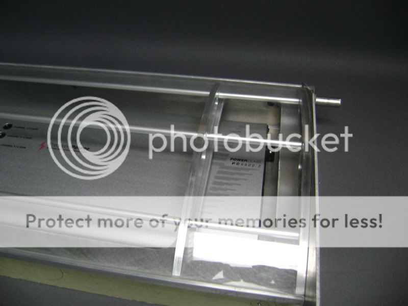
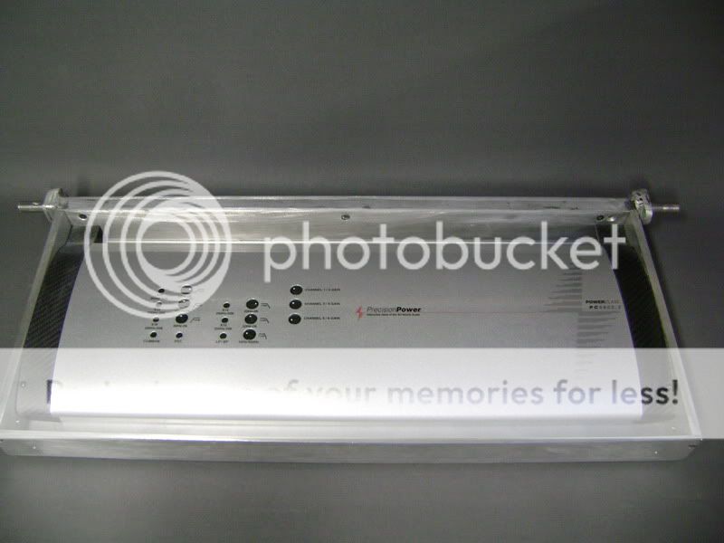
A picture here from the complete part, with the plexi on.I will have to screw this tight still, so I stays right where it needs to be.
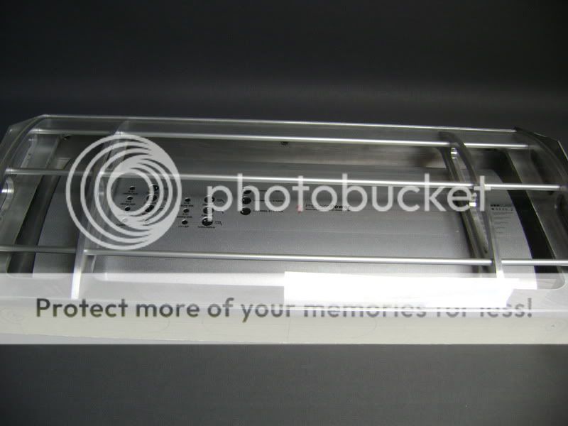
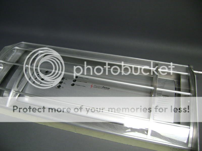
The whole part makes me feel that the amplifier is behind bars, in jail.
The 9 tubes you see on the fore-ground are from anodised aluminum.
On the backside you see 3 threadstaff of m6
Here you see why I had to sink in the m6 screws.
A picture here from the complete part, with the plexi on.I will have to screw this tight still, so I stays right where it needs to be.
The whole part makes me feel that the amplifier is behind bars, in jail.
Dec 2, 2011 | 02:25 PM
#149
Thread Starter
| Teamspeed Member
Joined: Jan 2008
Posts: 179
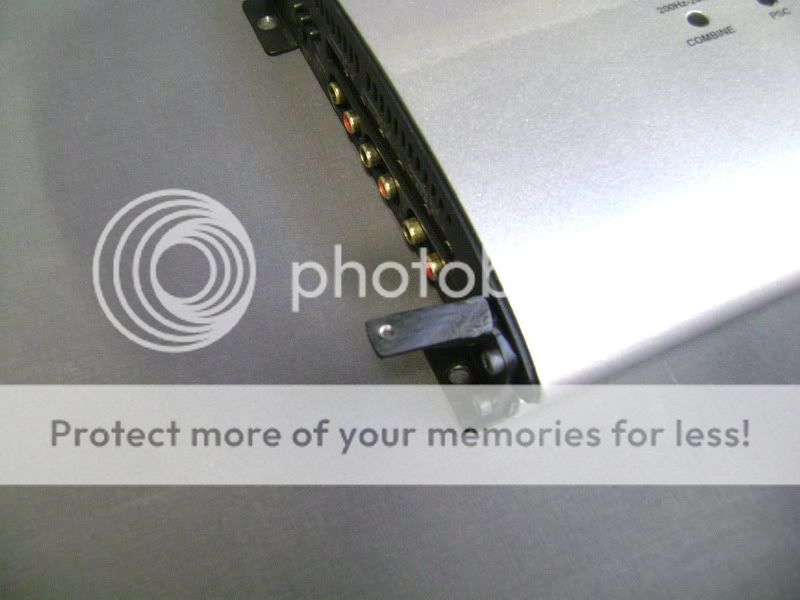
As you may see, on the left, and on the right, I have a gap of about 4cm for the cables (for the amp)
As you may know by now, I'm not a fan of cables in an install, so...
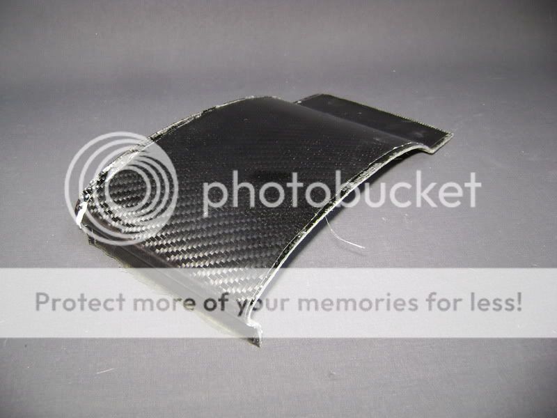
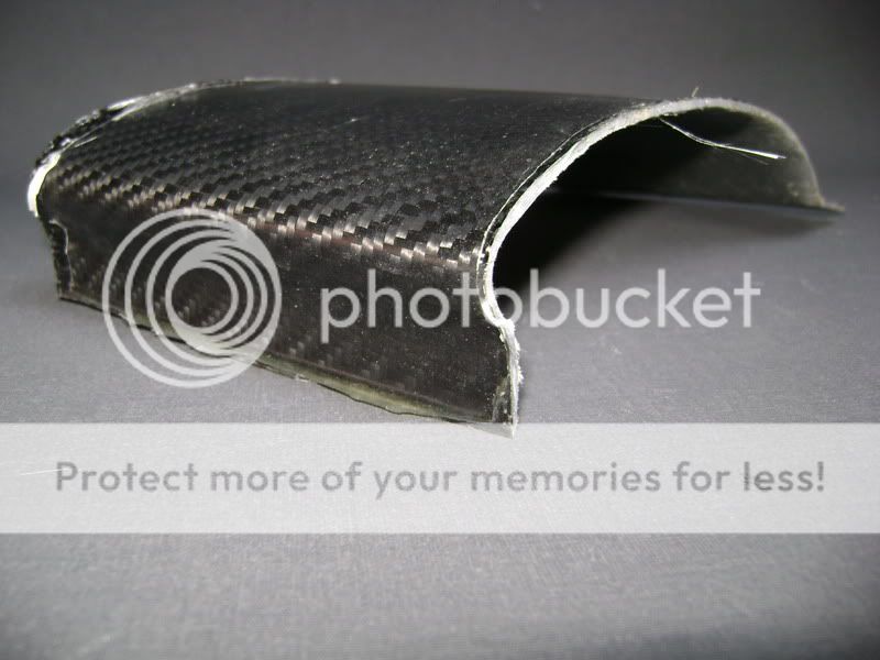
I made 2 pieces of carbon fibre for the sides, so the connections will not be visible.
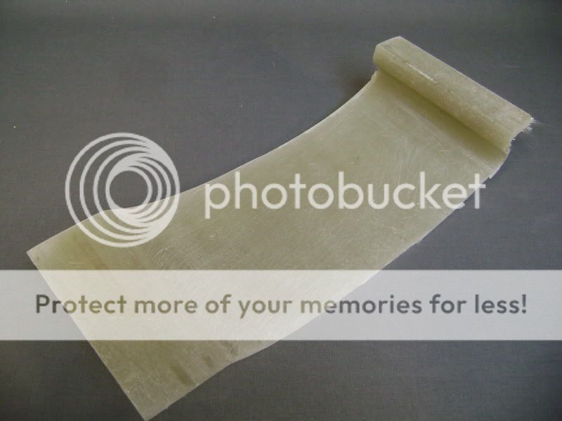
First, I made a fiberglass mold of the amplifier.
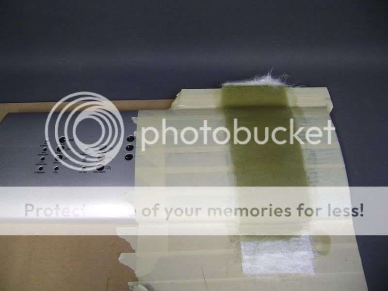

Once this was ready, I rubbed out the lines of the tape.
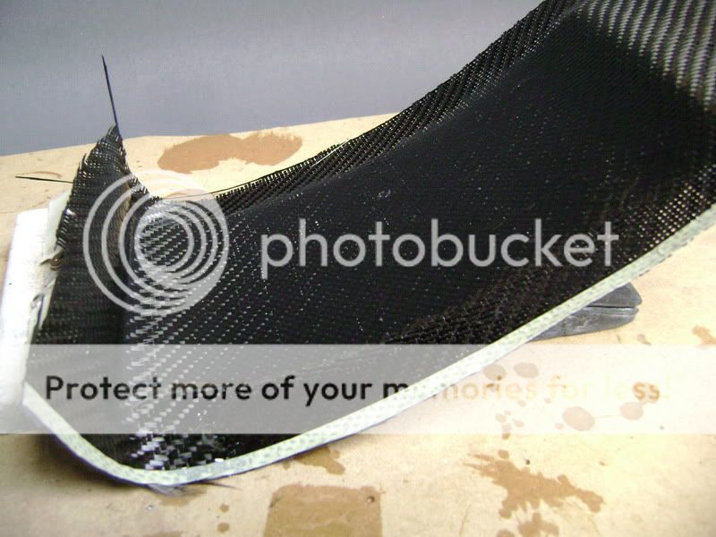
finished, so put on a layer of carbon in there.

By doing this , I learned something really stupid.
Because I never took a mold of thins I make, I don't have the necessary products here to do that.
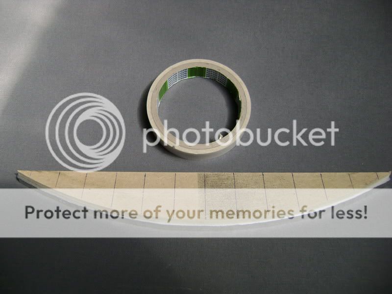
So I solved this on a idiotic way, really.
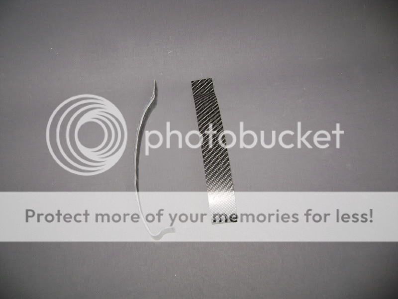
I just bought some plastic tape of 50cm? 50mmwss wide.
Taped it in the mold, and rubbed it in with polishing wax.
here you see the tape.

So you see, somethings will go with simple methods.
After this all, I put in the disc in the carbon fibre, and rubbed the piece nice and straight with my giant abrading block.

This is what I needed!
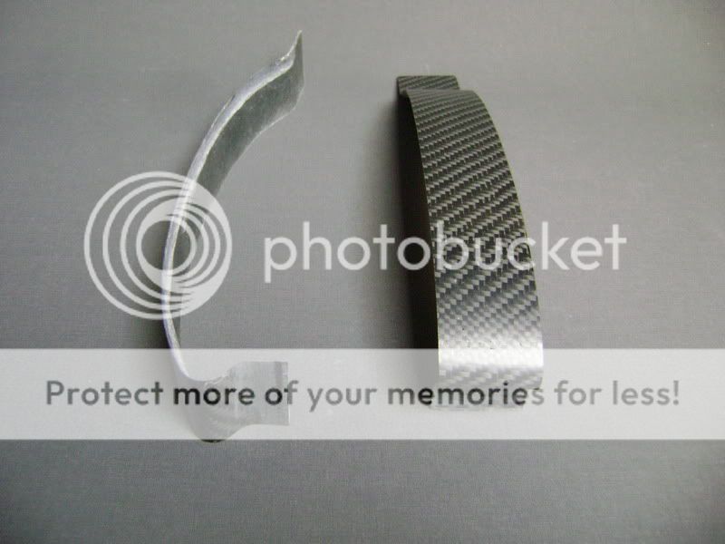
To tighten these 2 pieces, I have to make some aluminum toggles on the amplifier, so they connect with the rest nicely.
The carbon plates still need some layers of epoxy.
As you may know by now, I'm not a fan of cables in an install, so...
I made 2 pieces of carbon fibre for the sides, so the connections will not be visible.
First, I made a fiberglass mold of the amplifier.
Once this was ready, I rubbed out the lines of the tape.
finished, so put on a layer of carbon in there.
By doing this , I learned something really stupid.
Because I never took a mold of thins I make, I don't have the necessary products here to do that.
So I solved this on a idiotic way, really.
I just bought some plastic tape of 50cm? 50mmwss wide.
Taped it in the mold, and rubbed it in with polishing wax.
here you see the tape.
So you see, somethings will go with simple methods.
After this all, I put in the disc in the carbon fibre, and rubbed the piece nice and straight with my giant abrading block.
This is what I needed!
To tighten these 2 pieces, I have to make some aluminum toggles on the amplifier, so they connect with the rest nicely.
The carbon plates still need some layers of epoxy.
Dec 2, 2011 | 02:27 PM
#150
Thread Starter
| Teamspeed Member
Joined: Jan 2008
Posts: 179
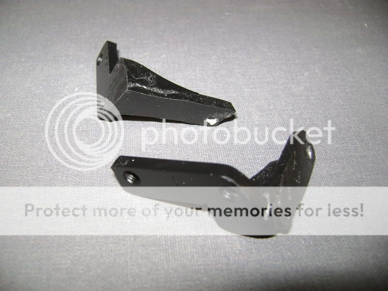
If made 2 toggles to tighten the carbon pieces onto the amlpifier.
Here , everything is on the amplifier.

You can see I only put in 1 screw.
The carbon fibre sits in between the aluminum and the amplifier, tight as a rock.
When the cover is on, you aren’t gonna see that miserable screw anymore.
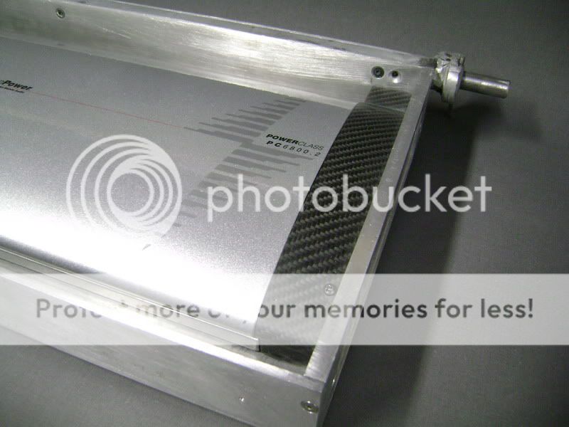
I also worked on the 2 sides of the amplifier-box.
I milled out as many aluminum as possible, where the cables will have to come.It will be tight, but we like it that way
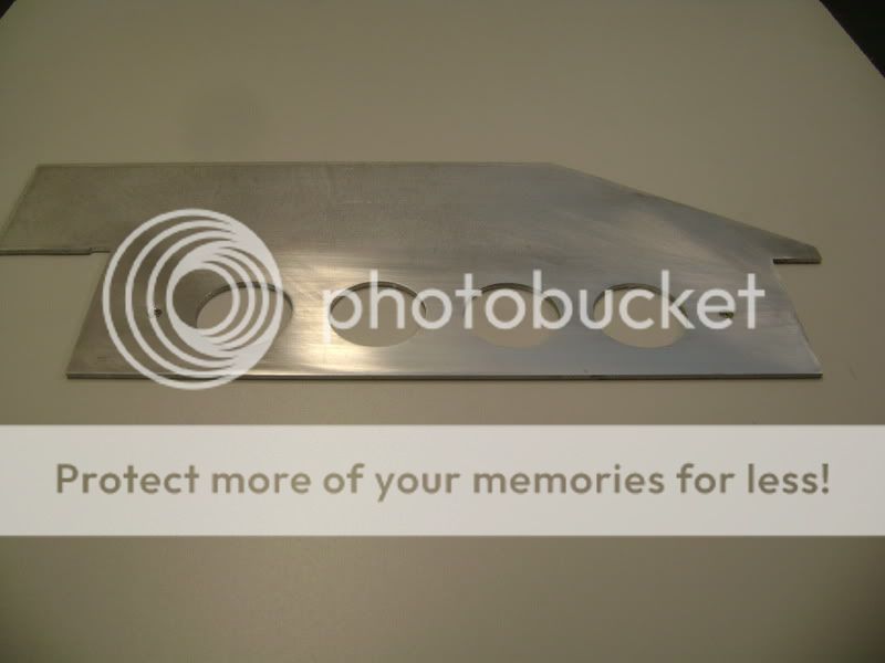
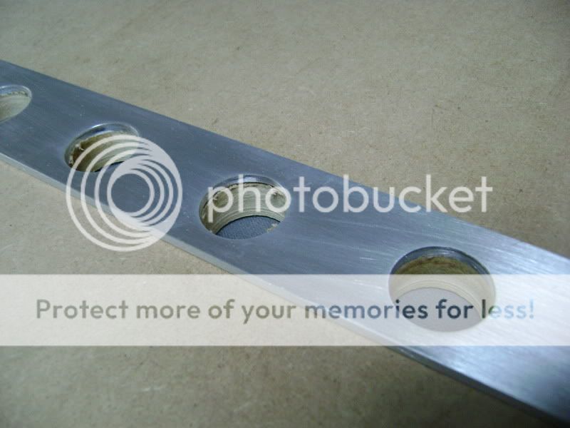
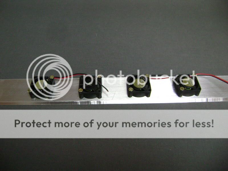
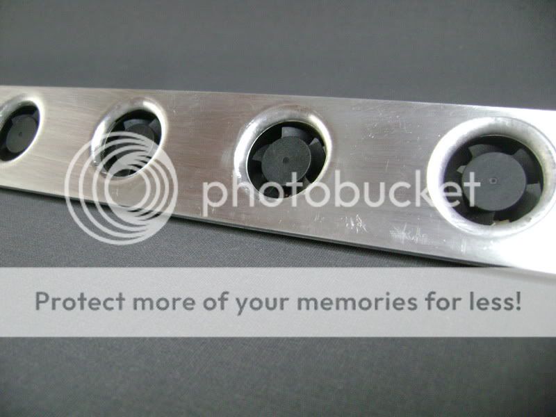
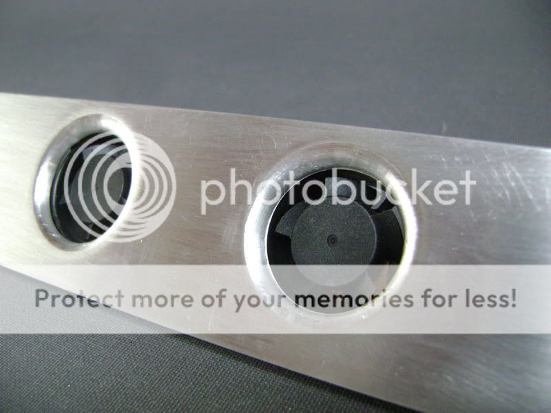
On this aluminum slat, I'm going to mount 4 little vents who gives some extra cooling on the PPI.Cause the "feed" part of the amplifier is on the right side, I also did it on that side.The aluminum plate is 4cm high and the vents are 2.8cm big.
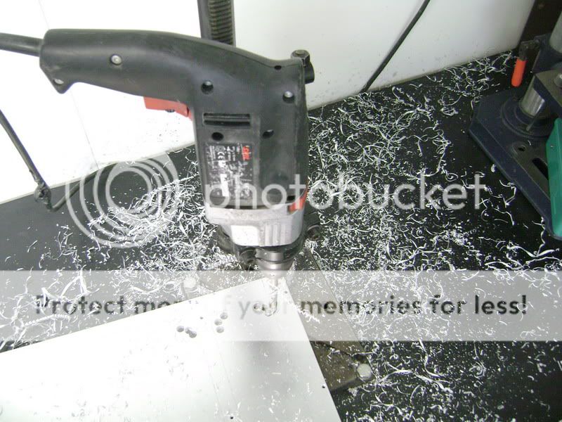
These 4 wholes, I drilled with a "step"drill

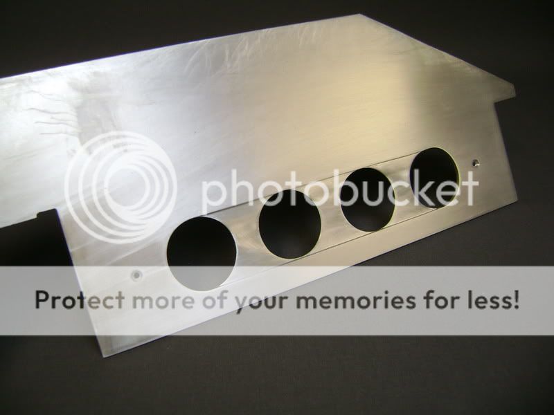
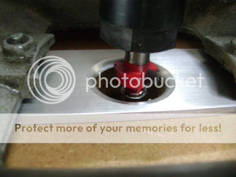
Then I glued the slat on a piece of mdf, and made the wholes as big as the aluminum with the uppermill
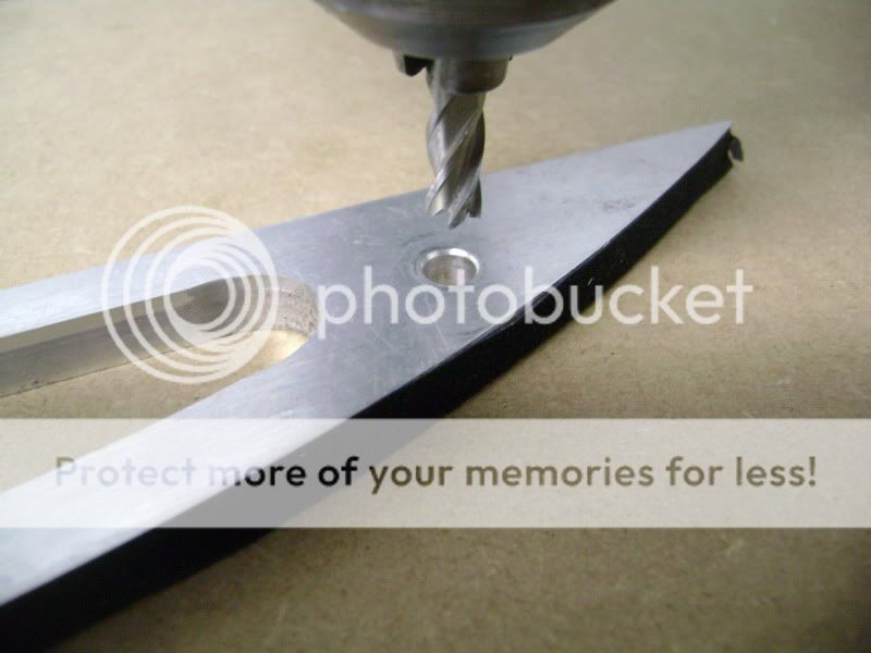
Then I took the mill, to round up the frontside of the aluminum, and so it's all milled nicely.
Then I milled the backside of the slat diagonal
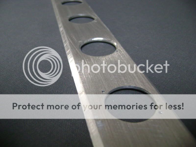

after that I, carefely, drilled the wholes, who will serve to tighten the vents.
I used some normal wood-screws fot that.
This is how it looks on the frontside.
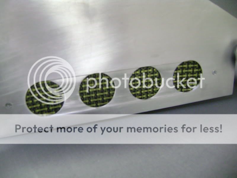
The meaning now is to polish that slat of aluminum, and put a layer of carbon fibre over that.Once this is all finished, I'm going to put in the uppermill again, to round up the frontside.
The meaning is that you'll see the aluminum that's rounded.
If this is possible, I'm not sure. HAven't done it myself either...but , there's a first time for everything!
Here , everything is on the amplifier.
You can see I only put in 1 screw.
The carbon fibre sits in between the aluminum and the amplifier, tight as a rock.
When the cover is on, you aren’t gonna see that miserable screw anymore.
I also worked on the 2 sides of the amplifier-box.
I milled out as many aluminum as possible, where the cables will have to come.It will be tight, but we like it that way
On this aluminum slat, I'm going to mount 4 little vents who gives some extra cooling on the PPI.Cause the "feed" part of the amplifier is on the right side, I also did it on that side.The aluminum plate is 4cm high and the vents are 2.8cm big.
These 4 wholes, I drilled with a "step"drill
Then I glued the slat on a piece of mdf, and made the wholes as big as the aluminum with the uppermill
Then I took the mill, to round up the frontside of the aluminum, and so it's all milled nicely.
Then I milled the backside of the slat diagonal
after that I, carefely, drilled the wholes, who will serve to tighten the vents.
I used some normal wood-screws fot that.
This is how it looks on the frontside.
The meaning now is to polish that slat of aluminum, and put a layer of carbon fibre over that.Once this is all finished, I'm going to put in the uppermill again, to round up the frontside.
The meaning is that you'll see the aluminum that's rounded.
If this is possible, I'm not sure. HAven't done it myself either...but , there's a first time for everything!